Story at a glance:
- Thermal bridging occurs when materials with a high heat conductivity are allowed to form an unbroken bridge between the inner and outer face of a building.
- Thermal bridges are a significant source of energy waste and can allow condensation to form, potentially leading to moisture damage or mold growth.
- Continuous insulation and the use of low-conductivity materials as thermal breaks can help to reduce the amount of thermal bridges in a building’s envelope.
As the second law of thermodynamics tells us, heat will always flow from hotter to colder regions of matter via the path of least resistance—and in buildings, these paths of least resistance are referred to as thermal bridges.

In this article we explore the basics of thermal bridging and provide insight into how to reduce the amount of thermal bridges in a building’s design.
What is Thermal Bridging?
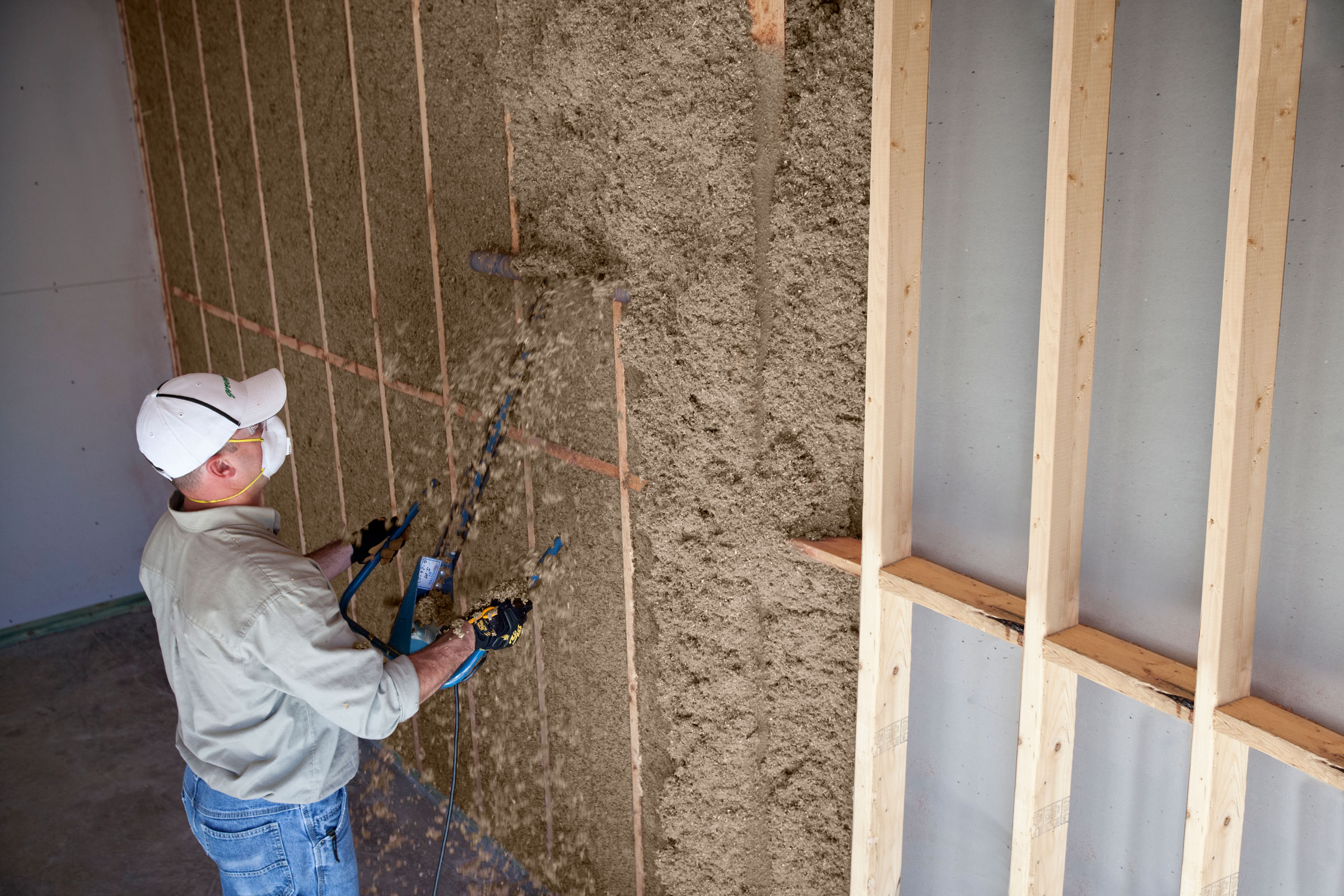
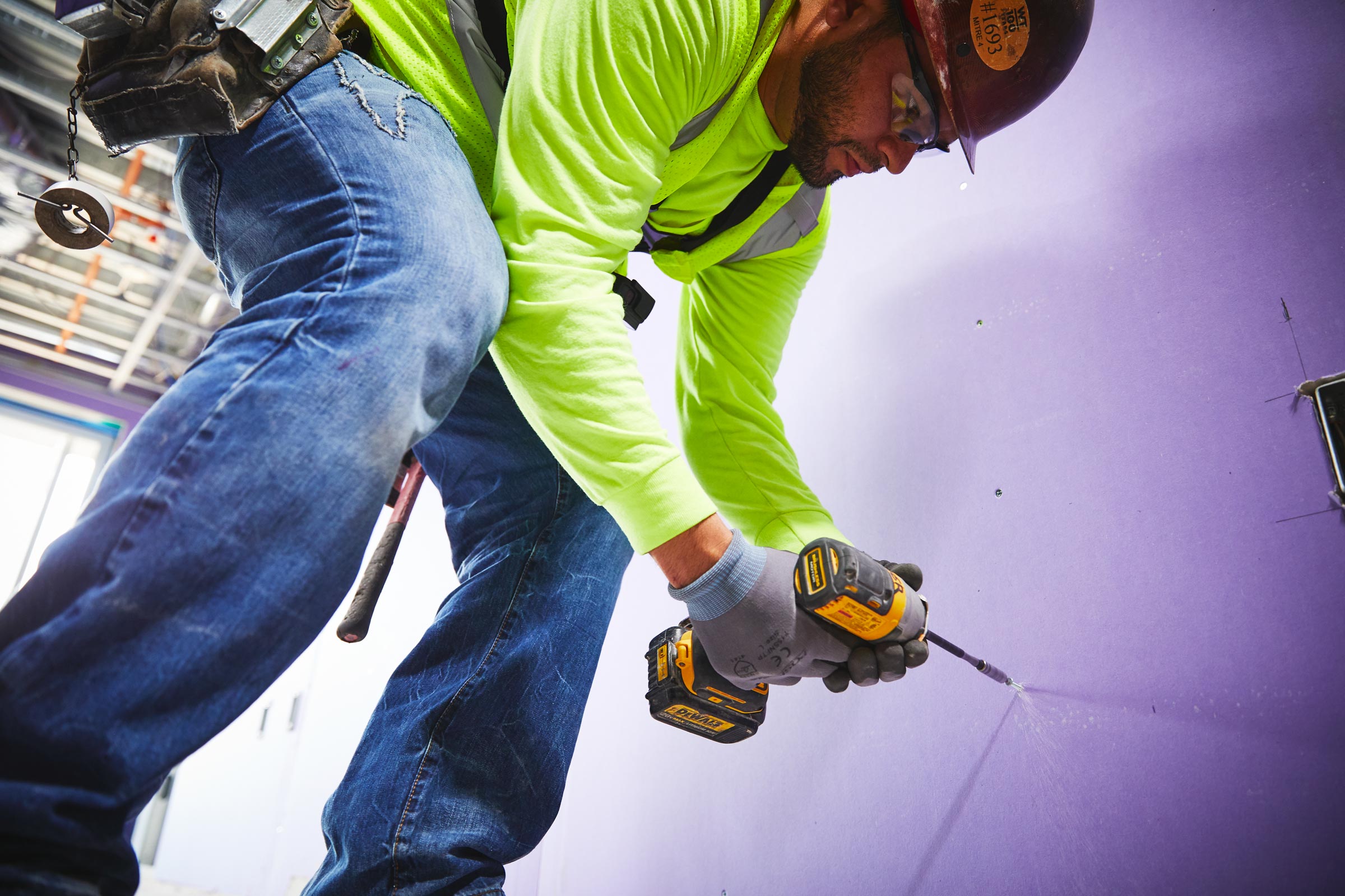
Thermal bridges are weak spots that interrupt a building’s insulation layer and allow heat transfer through the building envelope. Photo courtesy of Greenfiber
A thermal bridge, or cold bridge, is a weak area in a building’s envelope where heat is allowed to pass through from one side to another with little resistance. The International Passive House Association (iPHA) defines a thermal bridge as “a localized area of the building envelope where the heat flow is different (usually increased) in comparison with adjacent areas (if there is a difference in temperature between the inside and the outside).”
Thermal bridging typically occurs when a building component possesses a higher thermal conductivity than those materials surrounding it—thereby acting as a bridge for transferring heat—but the phenomenon can also occur as a result of the building’s geometry.
Thermal bridges may be identified in existing buildings using passive infrared thermography, a technology that detects heat signatures and thereby potential thermal leaks.
Where Does Thermal Bridging Occur?
There are a variety of places in which thermal bridging may occur within a building’s envelope, with the most common being:
- Fenestration. Windows and doors typically feature less insulation than the surrounding walls, especially when it comes to their frames and sashes, leading to thermal bridging around their edges.
- Framing systems. For homes especially, framing systems represent a large percentage of a building’s thermal bridges, as the studs and joists—be they wood, metal, or concrete—interrupt the insulation layer and facilitate heat transfer.
- Utility penetrations. Utility hardware like electrical wires, ducts, and plumbing often pass through the insulation layer and can act as thermal bridges.
- Balconies and parapets. Because the connection points for balconies and parapets pass through the building envelope, they can act as thermal bridges if the fixing detail is not adequately insulated.
- Fasteners and ties. While they do not create large thermal bridges, metal fasteners and ties in a building’s envelope are often numerous—which can drastically reduce total R-value.
All things considered, thermal bridges can occur just about anywhere if the design is poor or insulation is improperly installed.
Types of Thermal Bridging
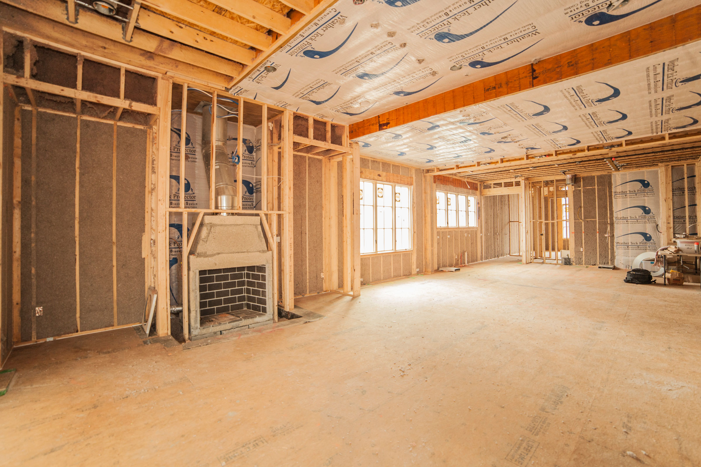
Material thermal bridges—like these wall studs and rafters—form literal bridges between the interior and exterior that facilitate heat transfer through the building envelope. Photo courtesy of Greenfiber
There are two basic categories of thermal bridges—material and geometric—that facilitate energy waste in slightly different ways.
Material Thermal Bridges
A material thermal bridge occurs at any point where a material, gap, or some other building component passes through or otherwise interrupts the insulation layer. This material or gap conducts heat better than the insulation, which effectively allows heat to transfer between the outside and inside.
Wall studs are a common example of material thermal bridges. Though they are important structural components, wood and metal wall studs interrupt insulation continuity, creating direct pathways for heat transfer. Similarly, any gaps left between insulation batts or boards will become thermal bridges.
Material thermal bridges can be reduced through strategic design choices during the planning stages of a project.
Geometric Thermal Bridges
A geometric thermal bridge may occur anywhere two or three different planes meet and does not form a literal bridge in the way that material thermal bridges do. Instead, geometric thermal bridges occur where the geometry of the envelope itself facilitates increased heat loss/gain in specific locations. These are typically locations where the heat absorbing surface is smaller than the heat-emitting surface, making the external heat loss area much greater than that of the area of its internal counterpart.
Geometric thermal bridges are particularly tricky in that they are entirely unavoidable, though they can be kept to a minimum by keeping building designs relatively simple. Common places where geometric thermal bridges occur include exterior wall corners, around window and door openings, eave junctions, and junctions between exterior walls and the ground floor.
Thermal Bridge Subtypes
The wooden wall studs in this house are a form of repeating thermal bridge. Photo courtesy of Greenfiber
Beyond material and geometric, there are also three core subtypes of thermal bridges: repeating, linear (non-repeating), and point.
Repeating
As the name suggests, repeating thermal bridges are interruptions spaced at regular, evenly distributed intervals throughout an element of the building envelope. The effect of repeating thermal bridges is typically factored into the U-value of building components. Wooden wall studs and steel wall ties in an insulated wall assembly are two of the most common forms of repeating thermal bridges.
Linear (Non-Repeating)
Linear or non-repeating thermal bridges, on the other hand, do not follow a set pattern per se but instead occur wherever there is a junction between elements. The heat lost from non-repeating thermal bridges is represented by the Greek letter Ψ and calculated using an advanced formula, for which there are calculators and software for.
Common examples include gaps in the insulation where the wall meets the floor, lintels above doors and windows, eaves, corners, and balconies.
Point
A point thermal bridge is best understood as a single penetration in a building envelope. Point thermal bridges include elements like isolated columns and beams, insulation fasteners, mounting brackets for canopies and awnings, and penetrations made by electrical cables.
It is extremely common for linear thermal bridges to be introduced after insulation has already been installed as a result of poor workmanship on the part of those laying the plumbing, doing the electrical work, et cetera.
Issues with Thermal Bridging
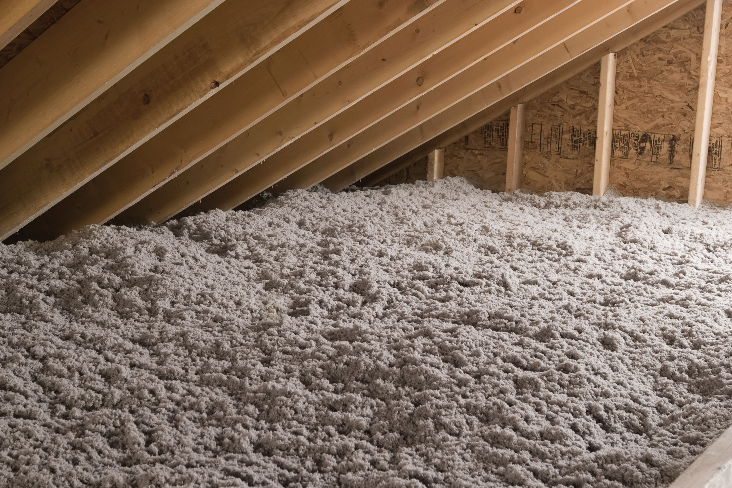
Thermal bridges waste energy and can facilitate condensation during the winter months, leading to moisture damage or mold growth. Photo courtesy of National Gypsum
While thermal bridging issues are unavoidable to a degree, they have become all too common in many modern development projects and represent a weak spot within the construction industry as a whole.
Energy Waste
Predictably, the biggest disadvantage of thermal bridges is that they are responsible for a not-insignificant amount of heating and cooling energy waste; research shows thermal bridging can account for as much as 30% of a building’s heat loss. This not only increases operational costs but also a building’s greenhouse gas emissions.
Thermal bridges also lower the overall R-value of a building component, which can lead to inaccurate performance estimates if the bridges are unaccounted for in an energy modeling scenario.
Condensation
Thermal bridges can also allow condensation to form during the colder months, potentially leading to moisture damage, mold growth, and even rot. This happens when warm humid interior air meets the cold surface of a thermal bridge, causing the ambient moisture to condense into liquid. This can happen both on the interior-facing side of a wall and inside the wall assembly itself, with the latter posing a threat to insulation integrity—resulting in worse performance and increased energy waste.
In cases of extremely low temperatures, this condensation can even lead to frost damage.
Reduced Comfort
Thermal bridges can also cause hot or cold spots to form in their vicinity, reducing the overall comfort level of a building’s occupants. A reduction in comfort can in turn cause poor productivity and ultimately detracts from a building’s indoor environmental quality.
How to Prevent Thermal Bridging
There are strategies to reduce the prevalence of thermal bridging in a project’s final design.
Continuous Insulation
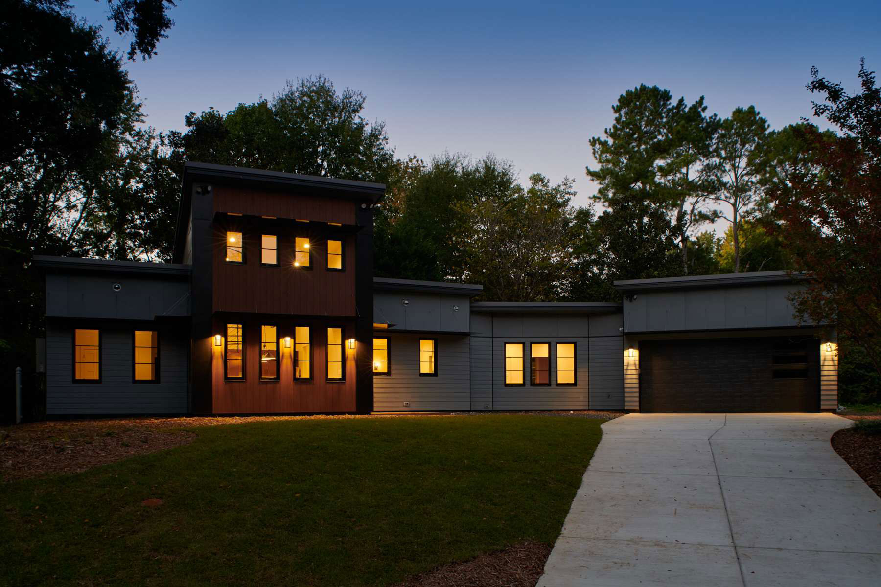
A contemporary three-bedroom house designed by LG Squared uses continuous stone wool insulation to keep the home a comfortable temperature while keeping energy demand low. Photo courtesy of LG Squared
The single most effective way of preventing thermal bridging is through the installation of continuous insulation. Continuous insulation is, by and large, exactly what it sounds like—insulation that is continuous across all structural members and which is free of thermal bridges save for those caused by fasteners and service openings. For maximum efficiency, high R-value materials like stone wool, extruded and expanded polystyrene, and polyurethane should be prioritized.
In areas where continuous insulation is not possible or feasible to implement, lapping the insulation of choice may suffice.
Structural Insulated Panels
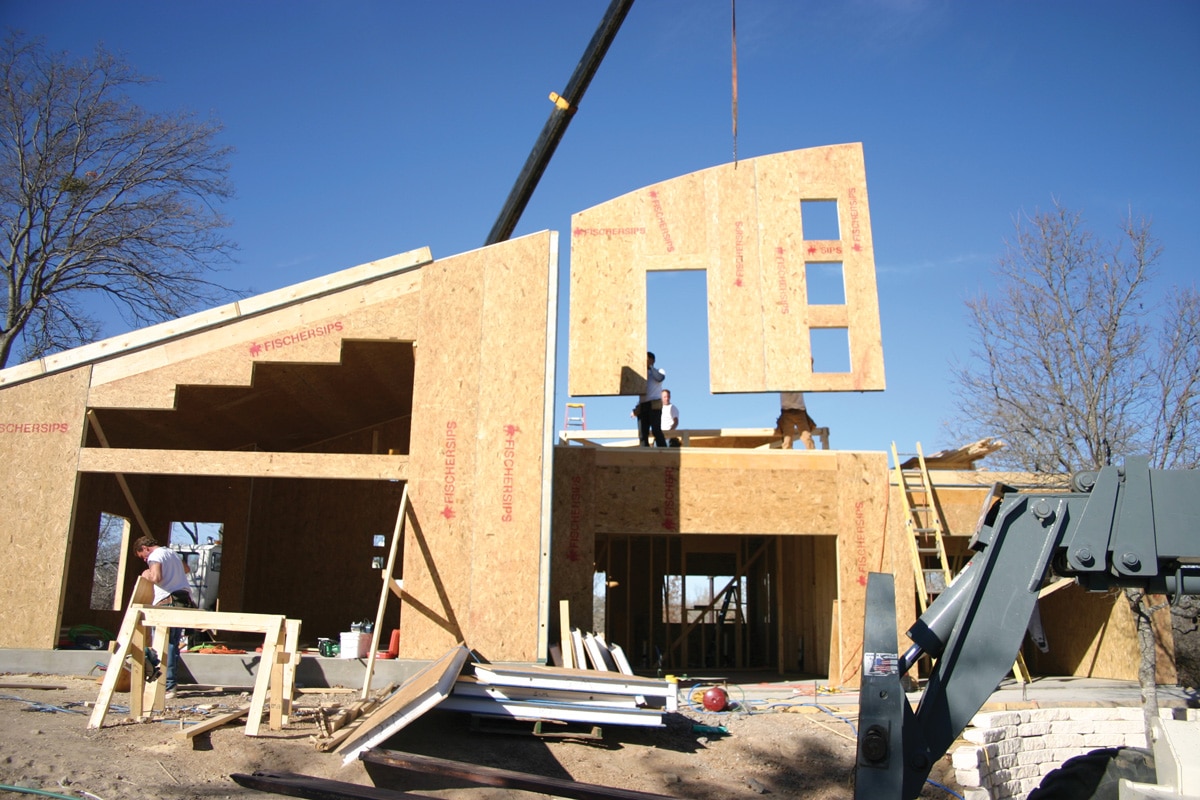
SIPs help provide continuous or nigh-continuous insulation and provide very few opportunities for thermal bridges. Photo courtesy of FischerSIPS
Structural insulated panels (SIPs) are a type of lightweight, high-performance composite paneling used in residential and light construction projects to create walls, floors, roofs, and even foundation systems. SIPs consist of two sheathing panels (typically oriented strand board, or OSB) sandwiched around an insulated foam core and can act as a form of continuous—or nigh continuous—insulation.
Of course, this is not to say that SIPs are inherently free of thermal bridges. Thermal bridges can, for example, occur at the splines between individual panels, of which have historically been fashioned from dimensional lumber. Other spline material options, however, are available, with composite and insulated lumber splines being ideal for projects looking to reduce thermal bridging.
What’s more, advancements in the OSB industry and prefabrication technology have allowed SIP manufacturers to create larger SIPs that make for tighter building envelopes with fewer opportunities for thermal bridging between panels.
Insulated Concrete Forms
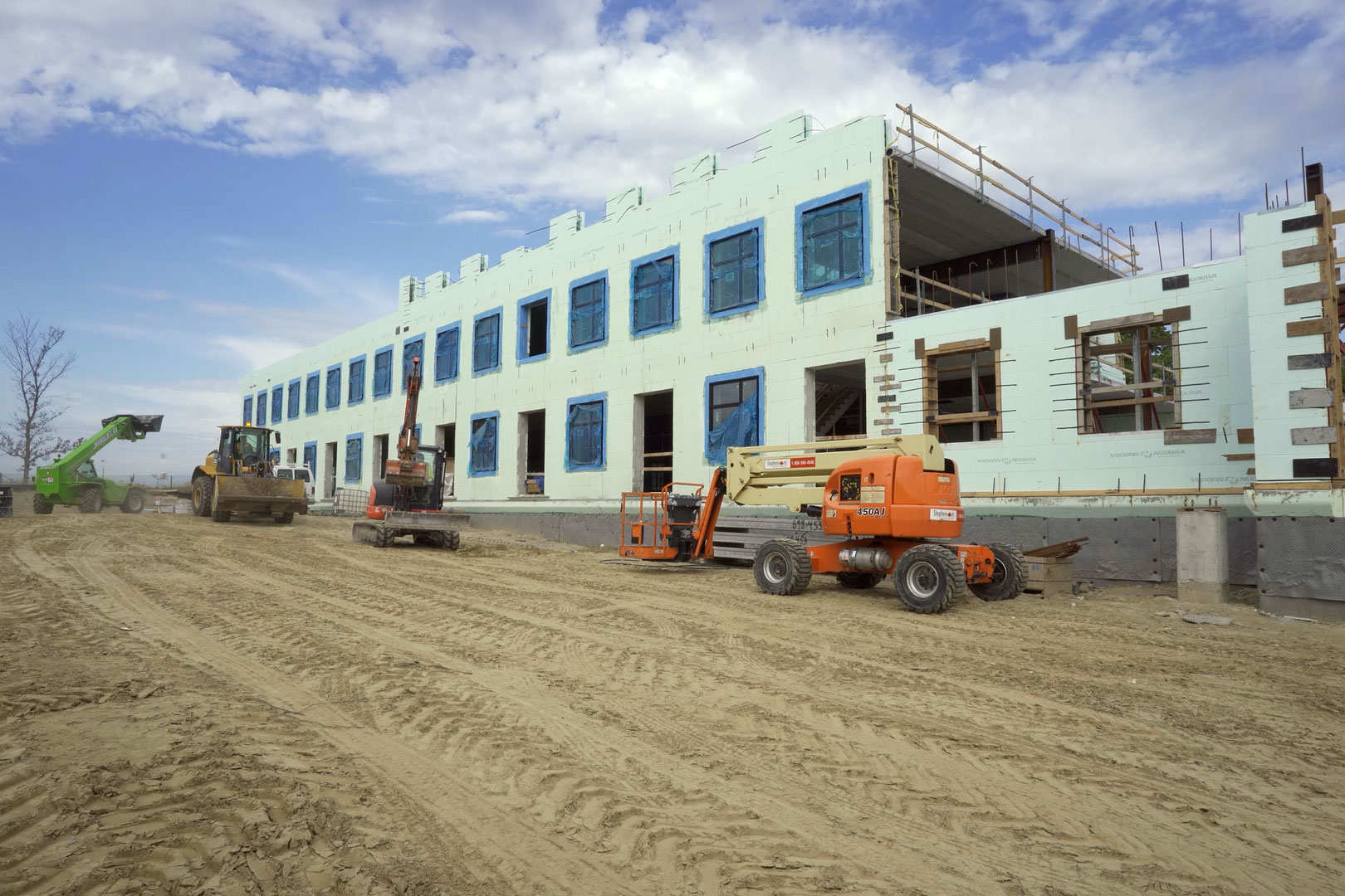
ICFs are free of thermal bridges and provide excellent thermal control, greatly reducing the need for mechanical heating and cooling. Photo courtesy of Tremco CPG Inc.
Insulated concrete forms (ICFs) can also help provide continuous insulation and greatly reduce the amount of thermal bridging in a project. Strong, quick to manufacture, and relatively simple to put in place, ICFs are created by pouring concrete into insulated polystyrene foam forms. Once the concrete sets, the forms are left in place rather than removed, giving the wall improved insulating qualities over traditional wood-frame walls. And as long as the footing underneath is also insulated, ICFs are virtually thermal-bridge-free—meaning their advertised R-value is what you’ll actually get.
“You can have a structural wall that delivers between an R-45 and R-55 with no more investment in materials and less investment in labor,” Brian Corder, marketing chair for the ICFMA and president of BuildBlock, previously wrote for gb&d. “If you want to design a building that will deliver extremely high energy performance, ICFs offer all of this and more.
In addition to their lack of thermal bridges, ICFs further help improve energy efficiency simply by being high mass building materials. “The building has so much mass, it takes a while for it to know that it’s gotten colder or warmer outside,” Cameron Ware, western division key account executive for Tremco CPG Inc.’s Nudara ICF brand, previously told gb&d. “This experience causes a reduction in peak loads for AC or geothermal equipment, so you can buy less equipment to satisfy that demand for that building.”
Thermal Breaks & Low Conductivity Materials
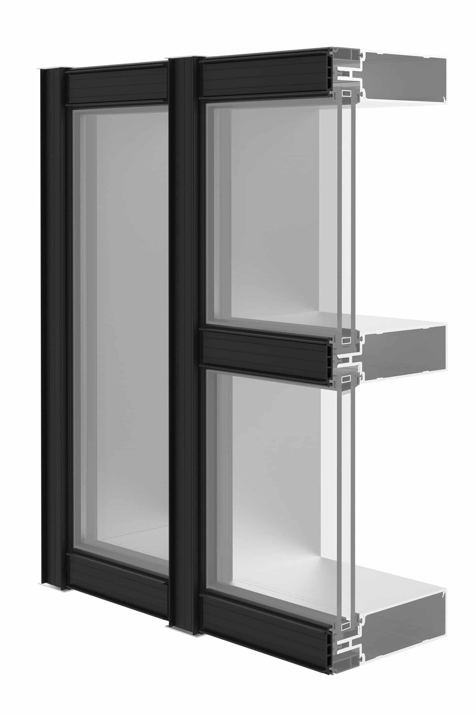
A polyamide pressure plate framework, which replaces the traditional aluminum plate, introduces a thermal break into this frame. Photo courtesy of YKK AP
Finally, thermal bridging can be reduced through the strategic use of thermal breaks, or material components with a naturally low thermal conductivity. This solution technically encompasses continuous insulation but ultimately includes any material that helps block the flow of heat.
Window frames and curtain walls, for example, are an infamous example of thermal bridge-prone areas—especially those made from highly conductive materials like aluminum. That’s why aluminum framing manufacturers began introducing thermal break technology into their designs to prevent unwanted heat transfer and energy waste. In the aluminum framing industry, one of two methods are typically used to introduce thermal breaks: pour and debridge or polyamide struts.
“A pour and debridge process creates thermal breaks and improves energy performance by filling a channel in the aluminum extrusion with a polyurethane material and then removing, or debridging, the bottom of the channel,” Steve Schohan, marketing and communications manager at YKK AP America, wrote in a previous gb&dPRO article. “The outside of the aluminum frame is thermally isolated from the inside of the aluminum within the glazing system. This process delivers strong energy savings economically.”
Polyamide struts, on the other hand, can be used to replace the aluminum pressure plate in traditional curtain wall systems. “A polyamide composition, for example, has significantly lower thermal transmission values than aluminum, providing structural and thermal performance that yields performance increases of up to 20% reduction in U-factor,” writes Schohan.
Thermal Bridging & Passive House Certification
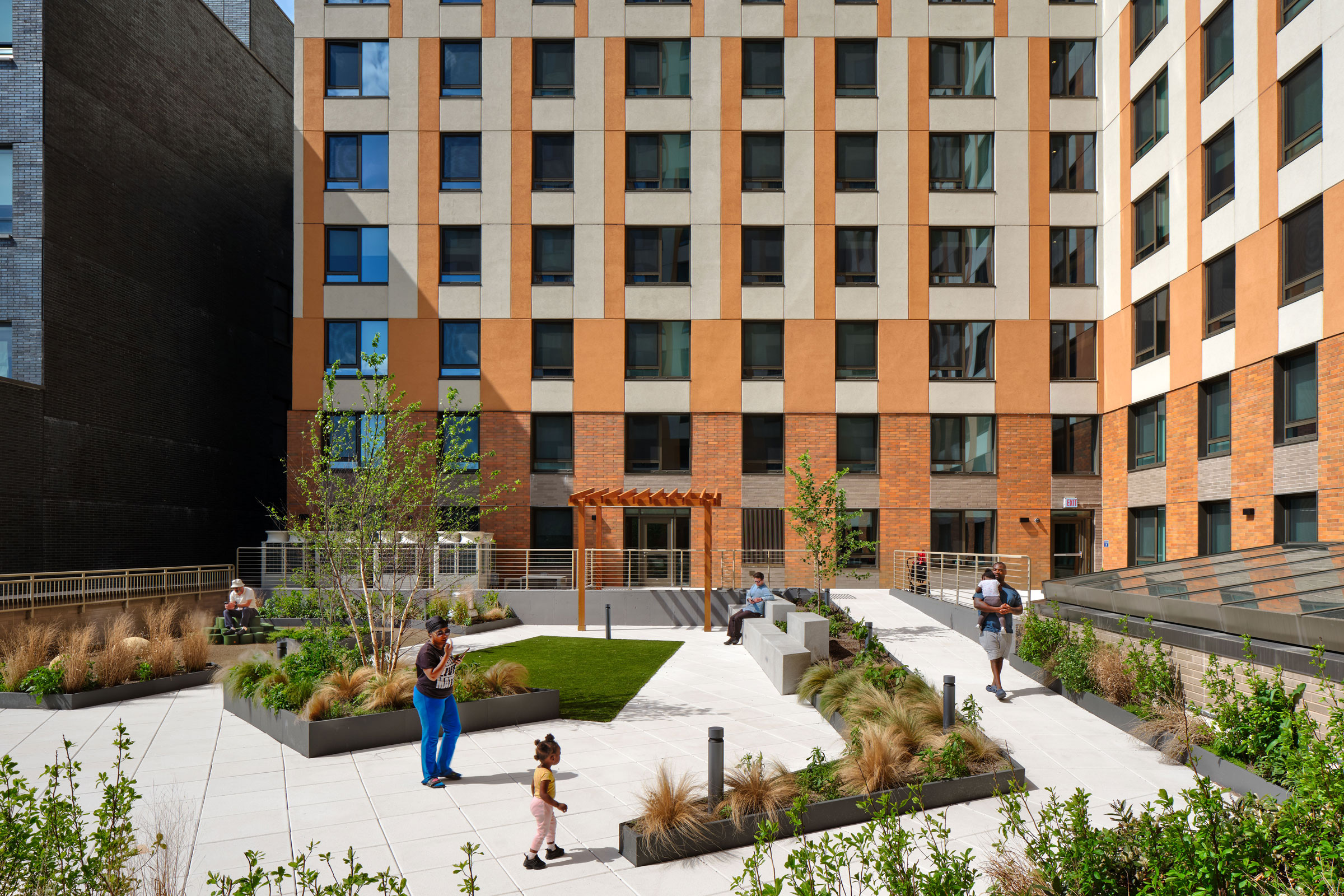
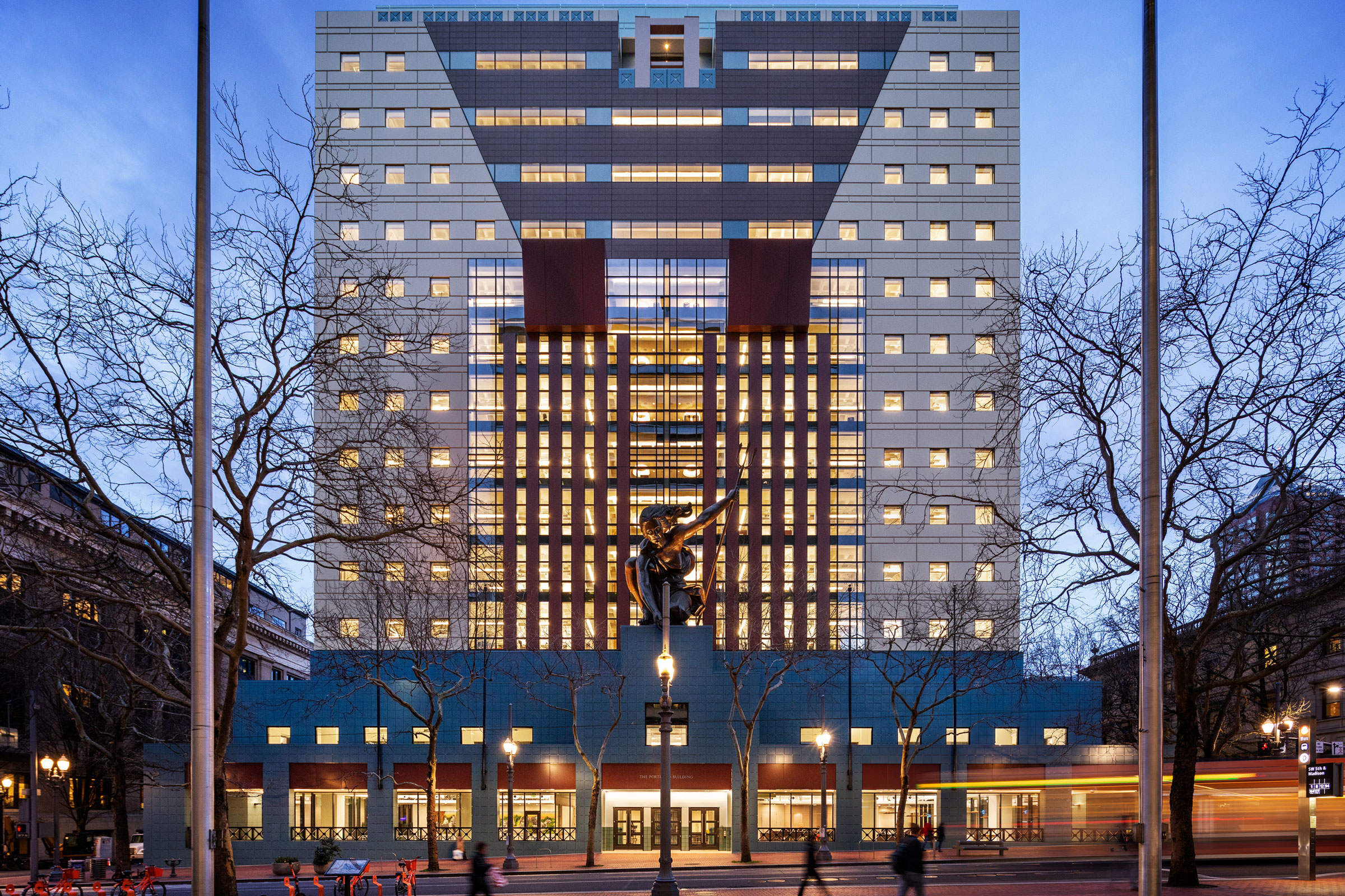
The 14-story Chestnut Commons building is designed to Passive House standards and is essentially free of unwanted thermal bridging. Photo courtesy of Phius
While there are many green building rating systems that emphasize energy efficiency and improved indoor environmental quality, few go to such lengths to eliminate thermal bridging as passive house certifying organizations. Both the Passivhaus Institute (PHI) and Phius specifically identify the reduction of thermal bridging as being integral to certification, with PHI going so far as to make thermal-bridge-free design one of the five core design principles.
It is possible to reduce thermal bridges to a point where they have a negligible impact on a project’s energy consumption. According to PHI, a Ψ value of 0.01 W/mK or less is technically considered thermal bridge–free.
The iPHA’s Passipedia has an entire catalog and several other resources dedicated to thermal bridges and achieving thermal bridge–free design.